Introduction
This programming assignment is intended to exercise a few useful data structures and an object-based view of a programming problem. There is some background reading, but the necessary program is not (or rather need not be) terribly big. The video walkthrough from Fall 2018 is located here.
We will be grading largely on whether you manage to get your program to work (according to our tests). In addition, we will be introducing you to writing your own tests by providing some examples and fill-in tests.
To obtain the skeleton files (and set up an initial entry for your project in the repository), you can use the command sequence
git pull skeleton master
from your Git working directory. Should we update the skeleton, you can use exactly the same sequence to update your project with the same changes.
Background
Warning: This section contains a significant amount of reading and it may be in your best interest to watch the video walkthroughs before skimming through this section.
You may have heard of the Enigma machines that Germany used during World War II to encrypt its military communications. If you have not, I recommend you read the wikipedia page on them, or similar resource, especially the part about design and operation. This project involves building a simulator for a generalized version of this machine, which will take descriptions of possible initial configurations of the machine and messages to encode or decode.
The Enigmas effect a substitution cipher on the letters of a message. That is, at any given time, the machine performs a permutation–a one-to-one mapping–of the alphabet onto itself. What separates the Enigma from a typical substitution cipher, however, is the fact that it implements a progressive substitution, different for each subsequent letter of the message, making decryption significantly more difficult.
The machine consists of a set of interchangeable rotors that sit side-by-side on a shaft and make electrical contact with each other. On each side of the rotor, there is an electrical contact which connects to a corresponding contact on the opposite side, creating a one-to-one mapping between the sides. To the left of these rotors, there exists a slot for a single reflector, which has contacts only on the side facing the rotors, creating a mapping from one half of the contacts to the other. An electrical signal which enters a contact in the rightmost rotor must therefore pass through each rotor, “bounce off” the reflector, and pass back through each rotor again by a different route, ending in a different contact than the original one entered.
Since each rotor and each reflector have different mappings and can be rotated, the overall permutation of a contact signal depends on their configuration: which rotors and reflector are selected, what order they are placed in the machine, and which rotational position they are initially set to.
Throughout the rest of the specifications, we will refer to the selected rotors in a machine’s configuration as 1 through N, with 1 being the reflector, and N being the rightmost rotor.
The overall permutation changes with each successive letter because some of the rotors rotate before encrypting a letter. Each rotor has a circular ratchet on its right half and an “alphabet ring” on its left half that fits over the ratchet of the rotor to its left. Before a letter of a message is translated, a spring-loaded pawl (lever)–one corresponding to each rotating rotor–attempts to engage the ratchet on the right half of its rotor and thus rotate its rotor by one position, changing the permutation performed by the rotor. Thus, pawls always try to engage with the ratchet of their own rotor. The lever on the rightmost rotor (N) always succeeds, so that rotor N (the “fast” rotor) rotates one position before each character. The pawls pushing the other rotors, however, are normally blocked from engaging their rotors by the alphabet ring on the left half of the rotor to their right.
This ring usually holds the pawl away from its own ratchet, preventing the corresponding rotor wheel from moving. However, the rings have notches in them (either one or two in the original Enigma machines), and when the pawl is positioned over a notch in the ring for the rotor to its right, it slips through to its own rotor and engages the ratchet. A “feature” of the design called “double stepping” is that when a pawl is in a notch, it is able to push nnot only the ratchet of its corresponding rotor, but the notch itself (and therefore, the rotor which contains the notch). Since the rotor \(i\)’s notch blocks rotor \(i - 1\)’s pawl from engaging with rotor \(i - 1\), when the pawl of rotor \(i - 1\) slips into the notch for rotor \(i\), rotors on both sides of the pawl move (the pawl for rotor \(i - 1\) moves both rotor \(i-1\) and rotor \(i\)).
Simplified Example
Let’s illustrate with a much simplified version. Suppose our alphabet has only the letters A-C and we have four rotors (numbered 1-4) each of which has one notch on its ring at the C position. Suppose also that there are 3 pawls, one for each of rotors 2-4. We will still refer to these as pawls 2-4, to maintain that pawl \(i\) belongs to rotor \(i\). There is no pawl for rotor 1, which will therefore not rotate. We’ll start with the rotors set at AAAA. The next 19 positions are as follows:
AAAB  AAAC  AABA  AABB  AABC  AACA  ABAB  ABAC
ABBA  ABBB  ABBC  ABCA  ACAB  ACAC  ACBA  ACBB
ACBC  ACCA  AAAB
As you can see,
- Rotor 4, the fast rotor, advances each time, pushed by pawl 4. Rotor 4 has no rotor to its right, so there isn’t a ring blocking it from engaging with its ratchet.
- Rotor 3 advances whenever Rotor 4 is at C. Rotor 4 has a notch at C, so pawl 3 can engage with the corresponding ratchet (the ratchet belonging to Rotor 3) and advance Rotor 3 by pushing on its ratchet. This would also rotate Rotor 4, since pawl 3 contacts its ratchet through the notch of Rotor 4, and therefore pushes the side of the notch when it moves. However, since Rotor 4 always rotates anyway (because pawl 4 is always unblocked), this doesn’t really change anything.
- Rotor 2 advances whenever Rotor 3 is at C, pushed by pawl 2. Rotor 3 has a notch at C, so pawl 2 slips into the notch and engages with its ratchet (the ratchet belonging to Rotor 2). Rotor 3 also advances when it is at C, because when pawl 2 is engaged through Rotor 3’s notch it will push against that notch when it moves, moving Rotor 3, as well as moving Rotor 2 by pushing on Rotor 2’s ratchet.
- There is no pawl 1, so Rotor 2 (unlike Rotor 3) does not advance just because it is at C.
- Rotor 1 never changes, since there is no pawl on either side of it.
Each rotor can only advance at most one position per keypress.
So the advancement of the rotors, while similar to that of the wheels of an odometer, is not quite the same. If it were, then the next position after AACA would be AACB, rather than ABAB.
Background cont.
The effect of advancing a wheel is to change where on the wheel any given signal enters or leaves. When a wheel is in its ‘A’ setting in the machine, then a signal that arrives from the right at, say, the ‘C’ position, goes into the ‘C’ contact on the wheel. Likewise, a signal that leaves the wheel from its left ‘C’ contact exits at the ‘C’ position. When the wheel is rotated by one to its ‘B’ setting, a signal that arrives at the ‘C’ position goes instead into the ‘D’ contact on the wheel, and a signal that leaves through the ‘D’ contact does so at the ‘C’ position. It’s easier to calculate if we use numbers 0–25 rather than letters (‘A’ is 0, ‘B’ is 1, etc.). Then, when the wheel is in its \(k\) setting, a signal entering at the \(p\) position enters the \(p+k \bmod 26\) contact on the wheel, and a signal exiting through the \(c\) contact does so at the \(c - k \bmod 26\) position. For example, Figure 1 shows one of the rotors from the real Enigma machines (called rotor “I”) and the effect of moving from its ‘A’ to its ‘B’ setting.
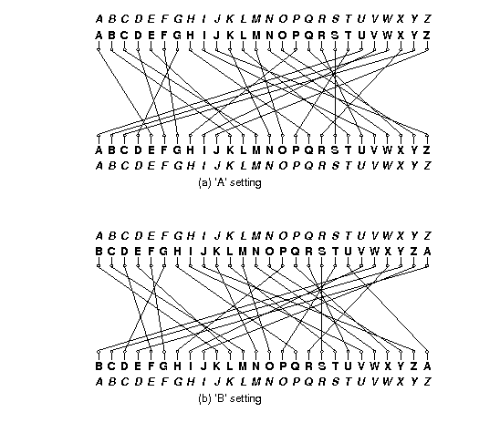
Figure 1. Permutations performed by a rotor in its ‘A’ and ‘B’ settings. The italicized alphabets at the top and bottom indicate the letters corresponding to the positions around the rotor. The inner alphabets indicate the positions along the rotor itself. The rotor depicted was designated ‘I’ in the original Enigma machine used by the German military.
The contacts on the rightmost rotor’s right side connect with stationary input and output contacts, which run to keys that, when pressed, direct current to the contact from a battery or, when not pressed, direct current back from the contact to a light bulb indicating a letter of the alphabet. Since a letter never encrypts or decrypts to itself after going back and forth through the rotors, the to and from directions never conflict.
The German Navy used a machine with 12 rotors and five slots for them:
- Eight rotors labeled with roman numerals I–VIII, of which three will be used in any given configuration as the rightmost rotors,
- Two additional non-moving rotors labeled “Beta” and “Gamma”, of which one will be used in any configuration, as the fourth-from-right rotor, and
- Two reflectors, labeled ‘B’ and ‘C’, of which one will be used in any given configuration as the leftmost rotor.
Given just this equipment, there are 614,175,744 possible configurations (or keys):
- Two possible reflectors, times
- Two possible rotors in the fourth position, times
- \(8!/(8-3)! = 336\) choices for the rightmost three rotors and their ordering, times
- \(26^4\) possible initial rotational settings for the rightmost four rotors (each reflector had only one possible position.).
Especially by today’s standards, this is not a large key size (less than 30 bits). To make things more difficult for code-breakers, therefore, the Enigma incorporated a plugboard between the keyboard and the rightmost wheel. It acted as a non-moving, configurable rotor. The operator could choose any set of disjoint pairs of letters by means of cables placed between them on the plugboard. Each selected pair would then be swapped going into the machine from the keyboard and coming out into the indicator lights. Thus, if the operator connected the letters A and P, then P would be substituted for each A typed and vice versa. Likewise, if an ingoing letter was encrypted to P by the other rotors, it would display as A, and letters decrypted as A would display as P.
Describing Permutations
Since the rotors and the plugboard implement permutations, we’ll need a standard way to describe them. We could simply have a table showing each letter and what it maps to, but we’ll use a more compact notation known as cycle representation. The idea is that any permutation of a set may be described as a set of cyclic permutations. For example, the notation
(AELTPHQXRU) (BKNW) (CMOY) (DFG) (IV) (JZ) (S)
describes the permutation in Figure 1. It describes seven cycles:
- A maps to E, E to L, L to T, …, R to U, and U back to A.
- B maps to K, K to N, N to W, and W back to B.
- C maps to M, M to O, O to Y, and Y back to C.
- D maps to F, F to G, and G back to D.
- I maps to V and V back to I.
- J maps to Z and Z back to J.
- S maps to itself.
The inverse permutation just reverses these cycles:
- U maps to R, R to X, …, E to A, and A back to U.
- …
- S maps to itself.
Each letter appears in one and only one cycle, so the mapping is unambiguous. As a shorthand, we’ll say that if a letter is left out of all cycles, it maps to itself (so that we could have left off “(S)” In the example above.)
Figure 2 shows the permutations corresponding to the rotors used in the German Navy’s Enigma machine.
| Rotor | Permutation (as cycles) | Notch |
|---|---|---|
| Rotor I | (AELTPHQXRU) (BKNW) (CMOY) (DFG) (IV) (JZ) (S) | Q |
| Rotor II | (FIXVYOMW) (CDKLHUP) (ESZ) (BJ) (GR) (NT) (A) (Q) | E |
| Rotor III | (ABDHPEJT) (CFLVMZOYQIRWUKXSG) (N) | V |
| Rotor IV | (AEPLIYWCOXMRFZBSTGJQNH) (DV) (KU) | J |
| Rotor V | (AVOLDRWFIUQ)(BZKSMNHYC) (EGTJPX) | Z |
| Rotor VI | (AJQDVLEOZWIYTS) (CGMNHFUX) (BPRK) | Z and M |
| Rotor VII | (ANOUPFRIMBZTLWKSVEGCJYDHXQ) | Z and M |
| Rotor VIII | (AFLSETWUNDHOZVICQ) (BKJ) (GXY) (MPR) | Z and M |
| Rotor Beta | (ALBEVFCYODJWUGNMQTZSKPR) (HIX) | |
| Rotor Gamma | (AFNIRLBSQWVXGUZDKMTPCOYJHE) | |
| Reflector B | (AE) (BN) (CK) (DQ) (FU) (GY) (HW) (IJ) (LO) (MP) (RX) (SZ) (TV) | |
| Reflector C | (AR) (BD) (CO) (EJ) (FN) (GT) (HK) (IV) (LM) (PW) (QZ) (SX) (UY) |
Figure 2. The rotors used in the Naval Enigma, showing the permutations they> implement and the point(s) at which there are notches that allow their left neighbor rotor to advance. Thus, when Rotor I is at ‘Q’ and the machine advances, the rotor to the left of Rotor I will advance. The Beta and Gamma rotors and the reflectors do not rotate. The reflectors shown here are the “thin” versions of the reflectors used in the naval M4 Enigma machine. The B reflector together with the Beta rotor in the ‘A’ position had the same effect as the usual (“thick”) B reflector in the older three-rotor M3 Enigma machine (likewise the C reflector with the Gamma rotor). This allowed the M4 to encrypt and decrypt messages to and from M3 Enigmas. Source: Tony Sale’s pages.
Example
As an example of a translation, consider the set of rotors from Figure 2, and suppose that
- The rotors in positions 1–5 are, respectively, B, Beta, III, IV, and I.
- The rotors in positions 2–5 are currently at positions A, X, L, E, respectively.
- In the plugboard, the letter pair ‘Y’ and ‘F’ and the letter pair ‘Z’ and ‘H’ are both interchanged.
We input the letter ‘Y’, which causes the following steps:
- The pawls all move. This causes rotor 5 to advance from E to F. The other two pawls are not over notches, so rotors 3 and 4 do not move.
- The letter ‘Y’ enters the plugboard and is converted to ‘F’.
- The letter ‘F’ enters the right side of rotor 5 (an I rotor) at position 5, since ‘F’ is the 5th letter of the alphabet numbering from 0. Since the current setting of rotor 5 is ‘F’, the signal enters the rotor at position \(5\), but hits contact \(5+5=10\), or ‘K’.
- According to Figure 2, rotor I converts ‘K’ to ‘N’ (letter number 13). Because the setting of rotor I is ‘F’, however, the signal actually comes out at letter position \(13-5=8\) (‘I’).
- The ‘I’ signal from rotor 5 now goes into the right side of rotor 4. Since rotor 4 is a IV rotor and is in the ‘L’ (or 11) setting, the ‘I’ enters at contact \(8+11=19\) (‘T’), and is translated to ‘G’ (6), which comes out at position \(6-11=-5 = 21 \bmod 26\), the fifth letter from the end of the alphabet (‘V’).
- The ‘V’ from rotor 4 goes now to the right side of rotor 3, a III rotor in setting ‘X’ (23). The signal enters the rotor at contact \(21+23 = 44 = 18 \bmod 26\) (‘S’), is translated to ‘G’ (6), which exits at position \(6 - 23 = -17 = 9 \bmod 26\) (‘J’).
- Rotor 2 (Beta) is in position ‘A’, and thus translates ‘J’ to ‘W’.
- Rotor 1 (B) converts the ‘W’ to ‘H’ and bounces it back to the left side of rotor 2.
- Rotor 2 (Beta in the ‘A’ position) converts ‘H’ on its left to ‘X’ (23) on its right.
- The ‘X’ from rotor 2 now goes into the \(23 + 23 = 46 = 20 \bmod 26\) (‘U’) contact on the left side of rotor 3 (III in setting’X’), and is converted to ‘W’ (22), which comes out at position \(22-23=-1=25 \bmod 26\) (‘Z’) on the right side of rotor 3.
- ‘Z’ now enters the left side of rotor 4 (IV in setting ‘L’) at \(25+11=36=10 \bmod 26\) (‘K’), and is translated to ‘U’ (20), which comes out at position \(20 - 11=9\) (‘J’) on the right side of rotor 4.
- The ‘J’ from rotor 4 enters the left side of rotor 5 (I at setting ‘F’) at contact \(9 + 5= 14\) (‘O’), is translated to ‘M’ (12), and comes out at position \(12 - 5 = 7\) (‘H’) on the right side of rotor 5.
- Finally,the letter ‘H’ is converted to ‘Z’ by the plugboard.
Therefore, ‘Y’ is converted to ‘Z’.
After a total of 12 characters are converted, the rotor settings will have become ‘AXLQ’. Just before the next character is converted, rotor 5 will advance to ‘R’ and, since its notch is at position ‘Q’, rotor 4 will advance to ‘M’, so that the rotor configuration will be ‘AXMR’ before the 13th character is converted. After an additional 597 characters have been converted, the configuration will be ‘AXIQ’. The character after that will advance rotor 5 to ‘R’ and rotor 4 to ‘J’, giving ‘AXJR’. The next character will advance 5 to ‘S’, and, since rotor IV’s notch is at ‘J’, rotor 3 will advance to ‘Y’. Also, as rotor 3’s pawl advances rotor 3, it also moves the notch on rotor 4, advancing rotor 4 to ‘K’, so that the configuration goes from ‘AXJR’ to ‘AYKS’. Rotor 3 in this case has a notch at ‘V’, but since rotor 2 has no pawl, rotor 3’s notch never has any effect.
Input and Output
This section contains information that has been implemented for you, but is made available in case you are interested. You only need to read this if you plan on using the Enigma machine after the project is done.
To run your program through IntelliJ, edit the configurations to run Main.java and supply the following as the program arguments:
testing/correct/default.conf testing/correct/trivial.inp
You can compare the output of this with the contents of testing/correct/trivial.out to see if your machine is outputting the correct results. To test against different files, simply replace the second argument (testing/correct/trivial.inp) with another input file (such as testing/correct/trivial1.inp).
The configuration file contains descriptions of the machine and the available rotors. The data are in free format. That is, they consist of strings of non-whitespace characters separated by arbitrary whitespace (spaces, tabs, and newlines), so that indentation, spacing, and line breaks are irrelevant. Each file has the following contents:
- A string of the form \(`C_1`\)
-\(`C_2`\) where \(`C_1`\) and \(`C_2`\) are non-blank characters other than “-”, “(”, and “)”, with \(`C_1\le C_2`\). This specifies that the alphabet consists of characters \(`\ge C_1`\) and \(`\le C_2`\), with lower-case letters mapped to upper-case.
Unless you do the extra credit, \(`C_1`\) and \(`C_2`\) will always be upper-case letters. - Two integer numerals, \(S > P \ge 0\), where \(S\) is the number of rotor slots (including the reflector) and $P$ is the number of pawls–that is, the number of rotors that move. The moving rotors and their pawls are all to the right of any non-moving ones.
- Any number of rotor descriptors. Each has the following components (separated by whitespace):
- A name containing any non-blank characters other than parentheses.
- One of the characters R, N, or M, indicating that the rotor is a reflector, a non-moving rotor, or a moving rotor, respectively. Non-moving rotors can only be used in positions \(2\) through \(S-P\) and moving rotors in positions \(S-P+1\) through \(S\).
- Immediately after the M for a moving rotor come(s) the letter(s) at which there is a notch on the rotor’s ring (no space between M and these letters).
- The cycles of the permutation, using the notation discussed above.
For example, the German Naval Enigma machine might be described with this configuration file (see Figure 2):
          A-Z
          5 3
          I MQ      (AELTPHQXRU) (BKNW) (CMOY) (DFG) (IV) (JZ) (S)
          II ME     (FIXVYOMW) (CDKLHUP) (ESZ) (BJ) (GR) (NT) (A) (Q)
          III MV    (ABDHPEJT) (CFLVMZOYQIRWUKXSG) (N)
          IV MJ     (AEPLIYWCOXMRFZBSTGJQNH) (DV) (KU)
          V MZ      (AVOLDRWFIUQ)(BZKSMNHYC) (EGTJPX)
          VI MZM    (AJQDVLEOZWIYTS) (CGMNHFUX) (BPRK)
          VII MZM   (ANOUPFRIMBZTLWKSVEGCJYDHXQ)
          VIII MZM  (AFLSETWUNDHOZVICQ) (BKJ) (GXY) (MPR)
          Beta N    (ALBEVFCYODJWUGNMQTZSKPR) (HIX)
          Gamma N   (AFNIRLBSQWVXGUZDKMTPCOYJHE)
          B R       (AE) (BN) (CK) (DQ) (FU) (GY) (HW) (IJ) (LO) (MP)
                    (RX) (SZ) (TV)
          C R       (AR) (BD) (CO) (EJ) (FN) (GT) (HK) (IV) (LM) (PW)
                    (QZ) (SX) (UY)
The input file to your program will consist of a sequence of messages to decode, each preceded by a line giving the initial settings. Given the configuration file above, a settings line looks like this: * B BETA III IV I AXLE (YF) (ZH) (all upper case.) This particular example means that the rotors used are reflector B, and rotors Beta, III, IV, and I, with rotor I in the rightmost, or fast, slot. The remaining parenthesized items indicate that the letter pair Y and F and the pair Z and M are steckered (swapped going in from the keyboard and going out to the lights).
In general for this particular configuration, rotor 1 is always the reflector; rotor 2 is Beta or Gamma, and each of 3-5 is one of rotors I-VIII. A rotor may not be repeated. The four letters of the following word (AXLE in the example) give the initial positions of rotors 2-5, respectively (i.e., not including the reflector). Any number of steckered pairs may follow (including none).
After each settings line comes a message on any number of lines. Each line of a message consists only of letters, spaces, and tabs (0 or more). The program should ignore the blanks and tabs and convert all letters to upper case. The end of message is indicated either by the end of the input or by a new configuration line (distinguished by its leading asterisk). The machine is not reset between lines, but continues stepping from where it left off on the previous message line. Because the Enigma is a reciprocal cipher, a given translation may either be a decryption or encryption; you don’t have to worry about which, since the process is the same in any case.
Output the translation for each message line in groups of five upper-case letters, separated by a space (the last group may have fewer characters, depending on the message length). Figure 3 contains an example that shows an encryption followed by a decryption of the encrypted message. Since we have yet to cover the details of File I/O, you will be provided the File IO machinery for this project.
             Input                              |         Output
* B BETA III IV I AXLE (HQ) (EX) (IP) (TR) (BY) | QVPQS OKOIL PUBKJ ZPISF XDW
FROM his shoulder Hiawatha                      | BHCNS CXNUO AATZX SRCFY DGU
Took the camera of rosewood                     | FLPNX GXIXT YJUJR CAUGE UNCFM KUF
Made of sliding folding rosewood                | WJFGK CIIRG XODJG VCGPQ OH
Neatly put it all together                      | ALWEB UHTZM OXIIV XUEFP RPR
In its case it lay compactly                    | KCGVP FPYKI KITLB URVGT SFU
Folded into nearly nothing                      | SMBNK FRIIM PDOFJ VTTUG RZM
But he opened out the hinges                    | UVCYL FDZPG IBXRE WXUEB ZQJO
Pushed and pulled the joints                    | YMHIP GRRE
   and hinges                                   | GOHET UXDTW LCMMW AVNVJ VH
Till it looked all squares                      | OUFAN TQACK
   and oblongs                                  | KTOZZ RDABQ NNVPO IEFQA FS
Like a complicated figure                       | VVICV UDUER EYNPF FMNBJ VGQ
in the Second Book of Euclid                    |
                                                | FROMH ISSHO ULDER HIAWA THA
* B BETA III IV I AXLE (HQ) (EX) (IP) (TR) (BY) | TOOKT HECAM ERAOF ROSEW OOD
QVPQS OKOIL PUBKJ ZPISF XDW                     | MADEO FSLID INGFO LDING ROSEW OOD
BHCNS CXNUO AATZX SRCFY DGU                     | NEATL YPUTI TALLT OGETH ER
FLPNX GXIXT YJUJR CAUGE UNCFM KUF               | INITS CASEI TLAYC OMPAC TLY
WJFGK CIIRG XODJG VCGPQ OH                      | FOLDE DINTO NEARL YNOTH ING
ALWEB UHTZM OXIIV XUEFP RPR                     | BUTHE OPENE DOUTT HEHIN GES
KCGVP FPYKI KITLB URVGT SFU                     | PUSHE DANDP ULLED THEJO INTS
SMBNK FRIIM PDOFJ VTTUG RZM                     | ANDHI NGES
UVCYL FDZPG IBXRE WXUEB ZQJO                    | TILLI TLOOK EDALL SQUAR ES
YMHIP GRRE                                      | ANDOB LONGS
GOHET UXDTW LCMMW AVNVJ VH                      | LIKEA COMPL ICATE DFIGU RE
OUFAN TQACK                                     | INTHE SECON DBOOK OFEUC LID
KTOZZ RDABQ NNVPO IEFQA FS                      |
VVICV UDUER EYNPF FMNBJ VGQ                     |
Quiz
Now that you have read through this much of the spec, complete the conceptual quiz before continuing. This quiz is optional and ungraded, but understanding the content of it is highly recommended before continuing.
Testing
We have supplied some basic tests in Permutaion.java, FixedRotor.java, Reflector.java, MovingRotor.java, and Machine.java. Follow the comment commands to run them.
Extra Credit
If you feel up to it, consider extending your program to work on more general alphabets. To specify an arbitrary alphabet, the first string in the configuration will be allowed to have the form \(`C_1C_2C_3\dots C_n`\), where the \(C_i\) are non-whitespace characters, not including lower-case letters, or the special characters “(”, “)”, “-”, or “*”. The standard \(`C_1`\)-\(`C_2`\) notation should continue to work, so that for example, A-Z is equivalent to ABCDEFGHIJKLMNOPQRSTUVWXYZ.
The effect of the more general specification is to specify the character set and the ordering of the characters along the rotors. For example, an alphabet specification of ACEDB means that the only characters in the alphabet are A-E, with A at the 0 position on each rotor, C at the 1 position, etc.
Debugging Tips
Although there are no separate times for debugging this project, feel free to talk to your fellow students (keeping in mind the collaboratio policies), lab TA, or come to Instructor OH.
In order to help us help you, if you are asking a member of Course Staff for help, please follow these steps:
-
Know what your question is before coming to ask for help. Writing down the question you plan to ask will oftentimes help you solve the issue without any help from others, and will make the process go more smoothly if you do, in fact, need help. Please preface your question with one of the following 3 sections of the project - Permutations, Rotors, Machine.
-
Document your code, including all methods you write, according to the style guide. This is to minimize time spent verbally explaining what each method does.
-
Make sure your code is well organized and explainable. It is not a good use of your time or the TAs’ time to try to find bugs in something that is disorganized and brittle. When we do provide debugging help, it may be at a high level, where we suggest ways to reorganize your code in order to make clarity and debugging easier.
-
If your question is about debugging a failed test, please attempt to have some sort of explanation for what might be causing the error. It might not be the case that you know exactly what is going wrong, but making sure you are thinking about what might be causing the error goes a long way towards avoiding future bugs in your code. Additionally, try to use the built-in IntelliJ debugger to help you narrow down and find the method or line where the bug might be located.
-
We will attempt to group students who have similar questions. This means you should talk to your surrounding neighbors and discuss possible approaches to each other’s bugs. You may not get 1-on-1 debugging help at times when lab is especially busy, but we can provide a high level plan of attack to identify and narrow down the causes of your bug.
What To Turn In
-
You should commit and push your completed project with the commit you want graded.
-
Your submission should contain no debugging print statements upon submission.
Advice
First, get started immediately, of course. Don’t just jump in and code, though. Watch the walkthrough videos, make sure you understand the specifications (which have their subtleties) and plan out how you’re going to meet them. Read the skeleton code and understand the design. Figure out how to break this problem down into small pieces, and how to implement and test them one piece at a time. Know in detail how you’re going to do something before writing a line of Java code for it. In particular, take some time to understand how the rotors work, and especially how the rotor position modifies the permutation.
There is a fair amount of string-hacking involved. The Java library can help you. Look at the documentation of String in the on-line Java library documentation. We particularly invite you to consider the constructors and the methods from String (charAt, replaceAll, split, startsWith, toUpper, trim, indexOf).
Be creatively lazy. Feel free to browse the Java library for useful stuff, even if you haven’t seen it in class.
If you find yourself writing the same or similar code repeatedly, try to take a step back and think about how to use for loops or if statements in a more creative way to generalize for the problem you are trying to solve.
Use the git repository. Frequently commit your work so that you’ll never have to reconstruct too much if your files somehow vanish mysteriously.
Above all, it is always fair to ask for help and advice. We don’t ever want to hear about how you’ve been beating your head against the wall over some problem for hours. If you can’t make progress, don’t waste your time guessing or bleeding: ask. If nobody’s available to ask, do something else (or get some sleep).
A Plan of Attack some TAs found useful was
- Start with
Permutation. - Next, move on to the various
Rotorclasses, going from least specific to most (Rotor -> FixedRotor -> Reflector -> MovingRotor). - Finally, fill in
Machine.
Common Bugs
%in Java is remainder, and has different behavior than you might expect with negative numbers. Please see the provided methodwrapfor modular conversions, or see what the body ofwrapdoes and replicate this if you prefer to use your own methods.